Why Canal Lining Matters — India's Water Loss Crisis
India's canal network spans over 180,000 km, distributing water from reservoirs to farmland across the country. However, unlined earthen canals suffer 40–50% conveyance losses through seepage — meaning nearly half the water released from a dam never reaches the farmer's field.
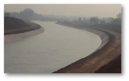
Canal lining addresses this by providing an impermeable barrier between the flowing water and the canal bed/sides. A well-constructed lined canal reduces seepage losses to under 5%, effectively doubling water delivery efficiency without building a single new dam.
The Government of India's CADWM (Command Area Development and Water Management) programme, AIBP (Accelerated Irrigation Benefits Programme), and PMKSY (Pradhan Mantri Krishi Sinchayee Yojana) have allocated thousands of crores for canal lining across states. Gujarat (Narmada canal network), Madhya Pradesh (Tawa canal, Bargi canal), Rajasthan (IGNP), and Maharashtra are the largest markets for canal lining contractors.
VRSIPL has lined over 800 km of canals across Gujarat and Madhya Pradesh — from distributary channels of 2m bed width to main canals of 30m+ bed width.
Types of Canal Lining
1. Cement Concrete (CC) Lining — The Gold Standard:
In-situ cement concrete lining (typically M15 grade, 75–100mm thick for minors and 100–150mm for main canals) is the most common and durable form of canal lining in India. It provides a design life of 40–60 years with minimal maintenance.
2. HDPE Geomembrane Lining:
A 500-micron HDPE sheet placed between the earthen canal section and a protective layer (often soil cement or stone pitching). Used where CC lining is uneconomical or where canal crosses highly permeable sandy soils. Design life: 20–30 years.
3. Brick/Stone Masonry Lining:
Older method using 230mm brick masonry or stone pitching with cement mortar pointing. Labour-intensive but still used for small village-level canals where mechanised lining is impractical.
4. Shotcrete Lining:
Sprayed concrete (gunite) applied 50–75mm thick — used for canal rehabilitation where the existing section geometry is irregular and conventional formwork is difficult.
5. Precast Panel Lining:
Prefabricated CC panels (typically 1m x 1m x 75mm) placed on prepared canal section and jointed. Used where site batching is impractical or where canal access is limited.
CC Canal Lining Construction — Step by Step
The construction sequence for cement concrete canal lining follows a precise methodology:
Step 1 — Canal Section Excavation:
Excavate the canal to the design trapezoidal section (typical side slopes 1.5:1 for lined canals). Use GPS-guided excavators for main canals and manual trimming for distributaries. Tolerance: ±30mm on bed, ±50mm on sides.
Step 2 — Sub-grade Preparation:
Compact the excavated surface to 95% Proctor density. Apply a 75mm gravel/murum sub-base on the canal bed and sides. This layer provides uniform support and prevents differential settlement of the lining.
Step 3 — Form Setting (Conventional Method):
For conventional (non-slip-form) construction, set steel channel forms along the canal sides at the specified lining thickness. Forms are checked for line, level, and slope.
Step 4 — Concrete Placement:
Pour M15 concrete (1:2:4 or 1:3:6 design mix depending on specifications) between the forms. Vibrate using plate vibrators on the bed and needle vibrators on the sides. Finish the surface smooth with steel trowels.
Step 5 — Curing:
Cure for minimum 14 days by ponding water on the bed and applying curing compound on the sides. In hot weather, extend curing to 21 days. Inadequate curing is the single biggest cause of canal lining cracking.
Step 6 — Joint Construction:
Transverse contraction joints at 3–5 metre intervals (12mm wide, sealed with polysulphide or bitumen). Longitudinal joints at the bed-side junction. Expansion joints at 30–50 metre intervals (20mm wide with compressible filler and sealant).
Step 7 — Dowel Bars and Toe Walls:
Dowel bars (12mm MS, 300mm long at 300mm c/c) at contraction joints to prevent differential displacement. Toe walls (300mm x 300mm CC) at the top of both canal sides to anchor the lining and prevent edge erosion.
Slip-Form Canal Lining — Mechanised High-Speed Method
Slip-form paving revolutionised canal lining productivity in India. A slip-form paver rides on the prepared sub-grade and extrudes a continuous concrete lining — bed and both sides simultaneously — at 50–150 metres per day.
How it works:
The machine carries a concrete hopper, vibrators, and a shaped mould (the slip-form). Concrete is fed into the hopper by transit mixers or concrete pumps. The machine moves forward on its tracks, leaving behind a finished lining surface that requires only joint cutting and curing.
Advantages:
- 5–10x productivity vs conventional method - Uniform lining thickness (no thin spots from poor formwork) - Better surface finish (lower Manning's 'n' value = higher flow capacity) - Lower labour requirement
When to use:
Main canals and branch canals with consistent cross-section and access for concrete supply trucks. Not suitable for canals with frequent structure locations, sharp curves, or restricted access.
VRSIPL operates slip-form canal liners that achieve 100–150 metres per day on main canal sections, supported by batching plants producing 30+ cum/hour of lining-grade concrete.
Quality Control in Canal Lining
Canal lining quality directly determines water-saving performance. Key quality parameters:
Concrete Strength:
Minimum 28-day cube strength of 15 N/mm² (M15). Test frequency: 1 set (3 cubes) per 50 cum or per day's work, whichever is more.
Lining Thickness:
Minimum specified thickness at every point. Check by core cutting at random locations — minimum 3 cores per km of lining. No core shall be less than 90% of specified thickness.
Surface Finish:
Smooth, dense, free from honeycombing. Roughness coefficient 'n' of 0.014–0.016 for CC-lined canals (vs 0.025–0.030 for unlined).
Joint Integrity:
All joints must be sealed without gaps. Sealant must bond to both faces of the joint groove. Failed joints allow seepage and lining panel displacement.
Sub-grade Compaction:
Field density tests at 100m intervals — minimum 95% Standard Proctor Density.
Seepage Test (Inflow-Outflow Method):
After lining completion, measure water loss per km by comparing upstream and downstream flow measurements. Acceptable limit: < 1.5 cumec per million sq.m of wetted area (IRC practice).
Related Topics
Continue Reading
Related Articles


Our Related Services
VRSIPL Services Covered in This Guide
Start Your Project
Have an Infrastructure Project?
Contact VRSIPL.
48 years of civil EPC delivery across India — WTP, STP, ETP, industrial civil, power plant, roads, and railways. Class-AA Gujarat. ISO 9001 | 14001 | 45001.